
Page 292 - 완) I MDP 프로젝트 작품 보고서(전체과 1학년)1.6
P. 292
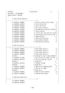
delay(2);                             /* Delay 50 ms                        */
               DeviceCode = rd_reg(0x00);
               if(DeviceCode == 0x9320)
               {
                       /* Start Initial Sequence
             --------------------------------------------------*/
                       wr_reg(0xE5, 0x8000);                 /* Set the internal vcore voltage     */
                       wr_reg(0x00, 0x0001);                 /* Start internal OSC                 */
                       wr_reg(0x01, 0x0100);                 /* Set SS and SM bit                  */
                       wr_reg(0x02, 0x0700);                 /* Set 1 line inversion               */
                       wr_reg(0x03, 0x1030);                 /* Set GRAM write direction and BGR=1 */
                       wr_reg(0x04, 0x0000);                 /* Resize register                    */
                       wr_reg(0x08, 0x0202);                 /* 2 lines each, back and front porch */
                       wr_reg(0x09, 0x0000);                 /* Set non-disp area refresh cyc ISC  */
                       wr_reg(0x0A, 0x0000);                 /* FMARK function                     */
                       wr_reg(0x0C, 0x0000);                 /* RGB interface setting              */
                       wr_reg(0x0D, 0x0000);                 /* Frame marker Position              */
                       wr_reg(0x0F, 0x0000);                 /* RGB interface polarity             */


                       /* Power On sequence
             -------------------------------------------------------*/
                       wr_reg(0x10, 0x0000);                 /* Reset Power Control 1              */
                       wr_reg(0x11, 0x0000);                 /* Reset Power Control 2              */
                       wr_reg(0x12, 0x0000);                 /* Reset Power Control 3              */
                       wr_reg(0x13, 0x0000);                 /* Reset Power Control 4              */
                       delay(5);                            /* Discharge cap power voltage (200ms)*/
                       wr_reg(0x10, 0x17B0);                 /* SAP, BT[3:0], AP, DSTB, SLP, STB   */
                       wr_reg(0x11, 0x0137);                 /* DC1[2:0], DC0[2:0], VC[2:0]        */
                       delay(2);                             /* Delay 50 ms                        */
                       wr_reg(0x12, 0x0139);                 /* VREG1OUT voltage                   */
                       delay(2);                             /* Delay 50 ms                        */
                       wr_reg(0x13, 0x1D00);                 /* VDV[4:0] for VCOM amplitude        */
                       wr_reg(0x29, 0x0013);                 /* VCM[4:0] for VCOMH                 */
                       delay(2);                             /* Delay 50 ms                        */
                       wr_reg(0x20, 0x0000);                 /* GRAM horizontal Address            */
                       wr_reg(0x21, 0x0000);                 /* GRAM Vertical Address              */


                       /* Adjust the Gamma Curve
             --------------------------------------------------*/
                       wr_reg(0x30, 0x0006);
                       wr_reg(0x31, 0x0101);


                                                         -  285  -